Review sample provided by Grimm Audio
Retail price including VAT: €4.999
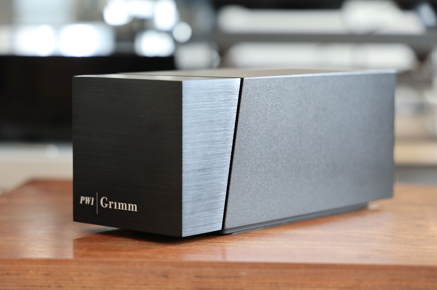
The PW1 MM/MC phono preamplifier is Grimm Audio’s latest product, released in January this year. The PW1 is an ideal companion for a Grimm Audio MU2 server/DAC/preamp or a Grimm Audio LS1 active loudspeaker system. Naturally, it also functions perfectly standalone in the context of any other audio system, and that is how I will review it.
Description
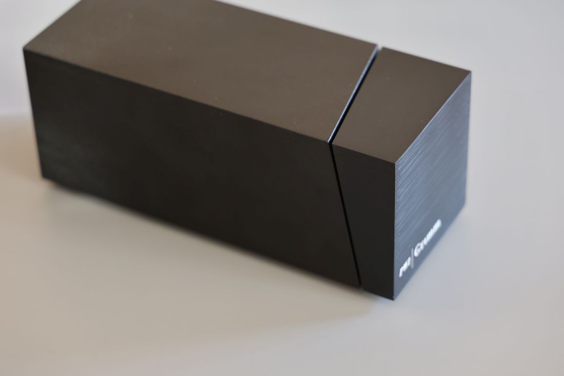
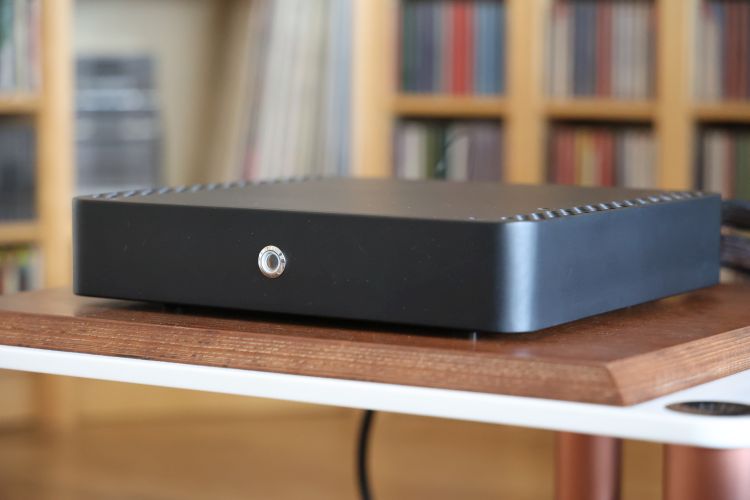
At 100mm x 100mm x 250mm (W x H x D), the PW1 is small enough to be placed anywhere, but with its sleek yet visually interesting industrial design by Michiel Uylings, you may not want to hide it from plain sight.
Grimm Audio’s co-founder Peter van Willenswaard spent a lifetime designing and improving phono preamps, both in solid-state and with tubes. Of all stages of audio amplification, phono preamplifiers pose the greatest challenges for a designer. With moving coil cartridges, deep bass signals of a mere 50 nV require no less than 90 dB amplification! Following many iterations, Peter managed to develop a solid-state phono preamplifier that challenges his best tube-based designs.
https://landing.grimmaudio.com/hfa_mu2https://www.grimmaudio.com/sales-points/hifi-sales/
Technical
Grimm Audio chose a design that minimizes components in the signal path, following the ‘KISS’ (Keep It Simple Stupid) and ‘Less Is More’ mottos: “What’s not in it cannot mess up the sound.” After all, an audio circuit aims to let as much music through while interfering minimally with the original recording. The more complex you make the circuitry, even if this is done to eliminate the circuit’s harmonic distortion, the greater the risk that you will hear the electronics involved.
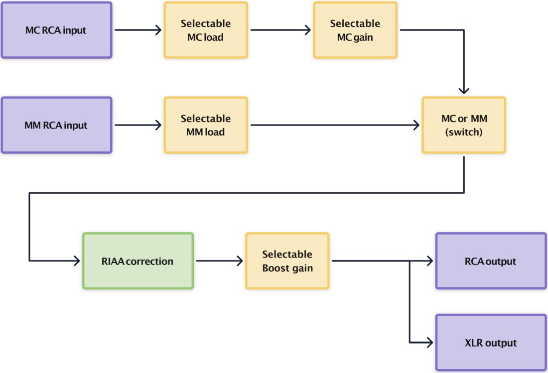
For the PW1, this means there is only one active component to bring the low voltage of an MC cartridge to the MM level. Then, there is only one active element to amplify the vulnerable input signal sufficiently so that the RIAA correction can perform its job flawlessly. After the RIAA correction, there is again only one active component to convey the RIAA-corrected signal flawlessly. Finally, there is a single, specially selected Op-Amp, the most musical specimen Peter could find, to serve as a buffer between the sensitive phono circuit and the load of cables and downstream equipment, offering a low output impedance among other benefits. Seemingly simple, but deceptively so.
As Peter van Willenswaard further explains in the White Paper:
“When taking the path of simplicity, you’ll have to go with the flow. You’ll have to accept the item you use, whether a FET, a Transistor, or an Op-Amp, for what it is. Because once you start to try and correct its peculiarities, you’ll be applying force and complicating things, which may, and probably will, lead you away from your goal. For example, I found it necessary to make one exception to the KISS rule: I let one bipolar transistor slip in! Why? To eliminate two unwanted properties of FETs that would harm the sound quality, because, as nice as FETs are, they are far from ideal. However, the correction is not done through force; the bipolar is used here in Cascode, an almost passive function with no signal gain, and as such, this does not compromise signal quality”.
One might ask: why don’t all manufacturers apply the same logic when simpler equals better? This is because it requires significant effort to design such a minimalist design properly. Due to the minimal amount of feedback, it is impossible to correct deviations, so this requires careful selection and extensive testing of both passive and active components. Furthermore, each amplifier stage needs a perfectly matched power supply, which must also be fine-tuned by ear.
Choosing the three active components before the Op-Amp buffer is essential. Grimm selected FETs (Field-Effect Transistors) for their high input impedance and favorable amplification characteristics compared to standard bipolar transistors. They are available with various amplification factors, reducing the need for further adjustments. For the moving coil (MC) input, the team utilized a FET with a low noise level of 0.7 nV/√Hz, resulting in a signal-to-noise ratio of 80 dB or higher. However, each FET must be individually measured and matched by channel, which requires specialized equipment and extensive testing during production to ensure product quality.
Using a passive RIAA network prevents distortion in the moving magnet (MM) stage and enables genuine dynamics. Significant care has been taken in the PCB layout and component placement. Such attention to detail may seem unnecessary, but Peter knows firsthand that poor design can have an adverse effect on sound.
While many designers aim for lower distortion, striving for figures around 0.001% can diminish sound quality, especially in phono stages. Although Grimm Audio typically prioritizes distortion figures, the inherent distortion of vinyl records means that low harmonic distortion in phono stages is far less critical. Grimm could therefore focus on minimizing the number of active components in the circuit, which has a substantial impact on the musical representation. Moreover, most of the distortion from the FET circuitry is an inaudible second-harmonic type. The single FET amplification stage and the absence of feedback correction explain why the PW1 has a relatively higher harmonic distortion figure compared to some competitors.
A key feature of the PW1 is that it doesn’t require a separate external power supply box, reducing the risk of hum and interference on the MC and MM inputs. In collaboration with Amplimo, the Grimm Audio team developed an extremely low-magnetic-field power supply transformer, designed by Guido Tent. It’s so well shielded that it can be placed directly above the MC input without adverse effects! Nevertheless, the transformer is positioned internally at a generous 20cm distance, ensuring the absence of noise. The cabinet is made from non-magnetic materials, using aluminum for the enclosure and a copper sub-chassis for enhanced shielding of the mains input and power supply.
Connections
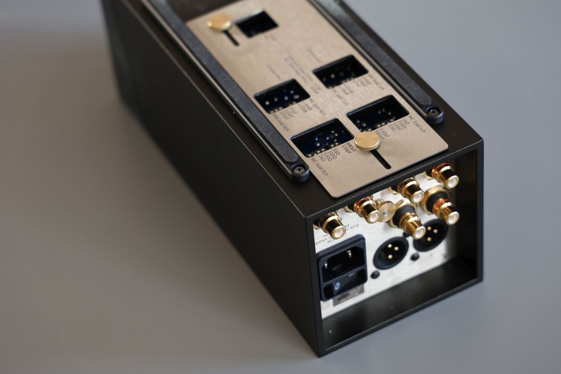
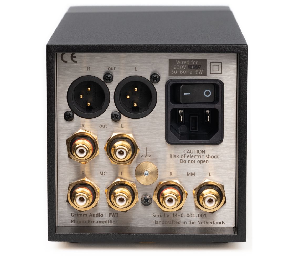
The PW1’s back panel is fully packed. The RCA connectors are very solid and well-spaced. The phono signal ground terminal is located in a tricky spot, making it somewhat difficult to access when the unit is fully connected, though it remains just within reach.
However, the XLR outputs’ sideways placement makes the Right channel connector’s release tab unreachable with my fingers. The solution is to disconnect the Left channel connector near the power inlet first. This orientation likely has sonic reasons stemming from the PCB layout, but it is not ideal for people who like to change cables now and then.
The RCA and XLR outputs are wired in parallel, incorporating a ground-compensating resistor on XLR pin 3. As a result, the XLR outputs are not truly balanced or differential, but this connection method is considered the purest, as it avoids the use of an extra operational amplifier (Op-Amp). Consequently, both outputs maintain the same signal level.
Next: Settings, Review Context, and Listening
Hi Christian,
I recently bought a Mola Mola Lupe and admired its sound: ultra-defined, fast, very powerful, and with tremendous dynamics and drive.
I ended up selling it because it didn’t sound like vinyl to me. It was too technical and dry.
Now reading the review, you describe it as smooth and seductive. I honestly don’t understand how you can describe it that way.
I’m looking for a phono preamp, and that’s why I’m interested in the Grimm, but your way of describing the Lupe puzzles me.
I think it depends on the context, expectations, focus points, and what other phono preamps you are used to. In relation to the Grimm PW1 and the other phono preamps I have heard before, to me, the Lupe is on the sophisticated, smooth, and composed side.
Hi -have the mola mola pre with the phono built in. It replaced my Ypsilon VPS-100/pst, phono and pre due to a downsizing. I ran them side by side playing vinyl from my kuzma X-L dc, 4pt and Lyra atlas. The mola mola easily matched the Ypsilon pair, certainly not laid back or lacking pace or rhythm.
I now use the mola mola with a lundhal silver sut playing from a technics sl1200g/blackbird arm which sounds even better than the kuzma.
Having experimented with vinyl for many decades the myriad interactions between; tt, arm, phono stage and phono cable can drive one crazy 🤪
It seems the only way to really get to grips with vinyl is through endless trial and error!
Hi Dave, yeah, I’m inclined to agree on the trial-and-error… With respect to my perception of something being expressive or laidback or anything in between, this is always in relation to my room, system, and preferences. It’s all relative. That is why I try my best to describe the variables and make as many comparisons as I can. That said, although the PW1 and a few others are livelier and more expressive, I have certainly also heard phono preamps that are more laidback than the Mola Mola.
I just took the leap on the PW1 after reading Christiaan’s review. I can confirm “effortlessly liquid” is a very accurate description. I’ve never heard 40K vinyl preamps and would not ever buy one, so can’t compare. But it’s hard to see why I would need something else at this stage. It sounds neutral to my ears. Not laid back yet not in your face, the opposite of thick, very precise yet silky. Soundstage is enormous but not vague or shifty. It’s like the walls fall away. I’ve heard slightly faster phono stages but by a small margin, nobody’s going to find this machine slow.
Surprisingly, despite all the possible settings, I do not find loading critical, I think I actually prefer running my Umami Red wide open at 47kohms. Differences are tiny (or maybe I’m deaf).
When “on”, I measured a consumption of 7W (6W announced, so all good): no nasty surprise here, contrary to other devices where specs can be overly optimistic…
Not audio-related, but I love the form factor and the design. The PW1 feels very luxurious.
The PW1 manages a rare feat: giving you the warm embrace of vinyl replay… without feeling warm. Nor cold.
Christiaan, I hope you’re still enjoying yours as much as when you bought it!
Thanks for your nice feedback, JB! I sure am still enjoying it!